|
|
Post by nhjeep on Aug 20, 2008 23:37:19 GMT -7
RE: power supplies
2) small breadboard device that augments a 'wall-wart' PC (this is the cheapest standalone option)
How would you generate the negative voltage from a wall-wart?
555 charge pump?
Or are you suggesting to find a wall-wart with a 30+ volt center tapped transformer?
Thx!
|
|
|
|
Post by chasw98 on Aug 21, 2008 4:45:42 GMT -7
Actually, the Elemental Designs eQ.2 uses a 30 volt center tapped wall wart. I am not sure where to buy that though. I have found the appropriate wall wart transformer on Mouser. If you go to the bottom of the page here www.geofex.com/Article_Folders/Power-supplies/powersup.htm you can see a schematic that will show you how to get bipolar voltage from a single ended source. It is not as efficient or capable as a true bipolar supply but it will work. Might be OK for sub use though. If you have any more questions, let me know. I will watch this thread and help you if you want. Chuck |
|
|
|
Post by ThomasW on Aug 21, 2008 7:21:57 GMT -7
We should add the $10 regulated medical PS linked to earlier in this thread works fine for this application. Chas is currently running one in a Marchand XM9 rebuild project we're working on, and we're planning on using them in more projects based on the Marchand PCBs that require +/- 5 VDC. 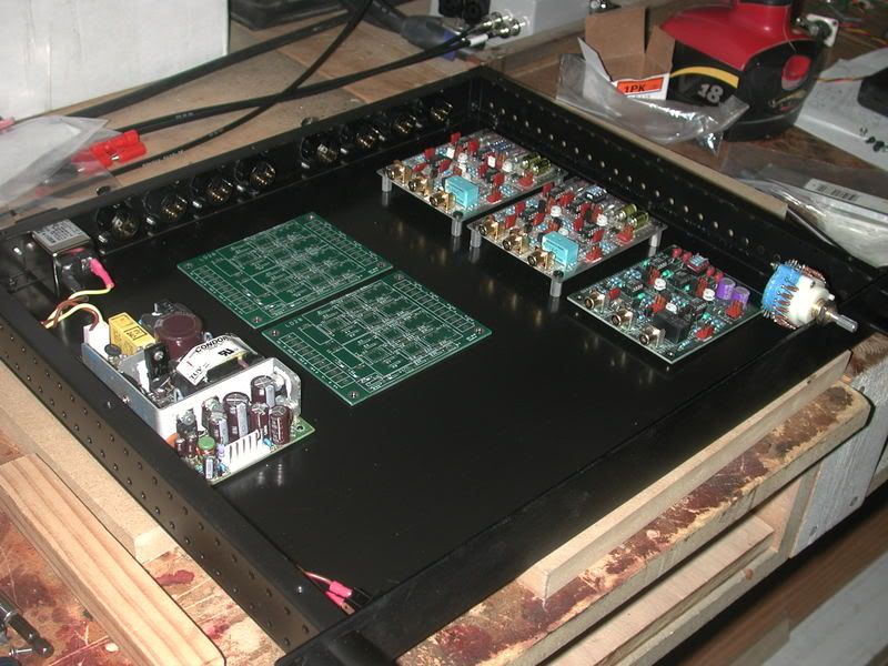 |
|
|
|
Post by chasw98 on Aug 21, 2008 10:15:43 GMT -7
We should add the $10 regulated medical PS linked to earlier in this thread works fine for this application. Chas is currently running one in a Marchand XM9 rebuild project we're working on, and we're planning on using them in more projects based on the Marchand PCBs that require +/- 5 VDC. +/- 15 VDC !  The little $10 supply has limitations. Be aware that it will do +15 volts DC @ 2 amps and - 15 volts DC @ 400 ma. And just so you know, this power supply is also available at Jameco for $147.29 www.jameco.com/webapp/wcs/stores/servlet/ProductDisplay?langId=-1&storeId=10001&catalogId=10001&productId=778040&The data sheets for the supply are available at the link if you want. |
|
|
|
Post by ThomasW on Aug 21, 2008 10:47:16 GMT -7
+/- 15 VDC ! Hey, let's not bash the dyslexic old geezer just because he makes a typo. I'm lucky to see the keyboard let alone type correctly .. ;D |
|
|
|
Post by ThomasW on Aug 21, 2008 11:09:55 GMT -7
I have the spreadsheet files and am trying to upload them. As usual Comcast's crappy hosting service is being problematic, so I don't know when they'll be available for download. The file is small so it can be sent as an attachment if needed... Edit. I pounded on the Comcast server enough times and finally it let me upload. Here's a download link for the spreadsheet home.comcast.net/~thomasw-2/halfspreadsheet.zip |
|
|
|
Post by chasw98 on Aug 21, 2008 13:58:16 GMT -7
+/- 15 VDC ! Hey, let's not bash the dyslexic old geezer just because he makes a typo. I'm lucky to see the keyboard let alone type correctly .. ;D Thats what keeps you young!!! |
|
|
|
Post by nhjeep on Aug 21, 2008 14:51:54 GMT -7
I was able to find an old wall wart in the basement rated for 15v. I cracked it open and to my happy surprise, I found a CENTER TAPPED transformer!  I removed two diodes and a cap, then used a full bridge rectifier, an LM7815, and an LM7915 to get my + & - voltages. Also a few caps per the datasheets. +/- 15V  And the spreadsheet just in time! Thank you! Now I'm getting ready to turn it all on - and getting a little nervous too! Any suggestions for a pre-flight checklist? i.e. before hooking it up to anything real? You Rock - Thanks for the datasheet! Sorry, I'm still a little fuzzy on the medical pwr supply... Since it's only +15v, how did you get the -15v output? If you used the tip that you posted just a little while ago, then you would have to tap the transformer in the supply. Is that what you are doing to power these projects? Or are you somehow inverting the voltage at the output of the supply? Thanks Chas!
Thanks Thomas!
Jon G. |
|
|
|
Post by ThomasW on Aug 21, 2008 15:45:27 GMT -7
|
|
|
|
Post by nhjeep on Aug 21, 2008 17:25:52 GMT -7
Ahhh, it has the taps on the transformer. Which means that you'd be bypassing (or at least altering) the rest of the circuit. So, wouldn't that mean that the 2nd supply would give the benefits of overload protection, fault recovery, yada, yada...? Or are you somehow taking advantage of those components when you tap for the negative voltage? Also, isn't the 2nd supply actually HERE: www.skycraftsurplus.com/index.asp?PageAction=VIEWPROD&ProdID=890for $10? 5.1, +/-15vdc Switching Power Supply, Board Type SK1335 Switching Power Supply, Multiple Output, 40 watt Detailed Description 5.1 Volts @ 4 Amps, +15 VDC @ 2 Amps, -15 Volts @ 0.4 Amps Triple Output "Board Type" Power Supply 100 - 240 VAC Input. Dimensions: L = 5", W = 3", H = 1-1/4" Condor Power Supplies GPM40B I didn't see a link for it posted here for Skycraft, but it's the one that Chas linked to over @ Jameco... Or am I mistaken? I'm having a brain-dead night, so bear with me...  BTW - SWEET lookin' box there! Thx for the pic! |
|
|
|
Post by nhjeep on Aug 21, 2008 17:43:53 GMT -7
POP! POOF! SIZZLE! Ack! DIVE FOR COVER! No wait, unplug it! Whew!!!!  I was prodding around the H@LF board with my voltmeter (specifically the XLR output), trying to see if there were any unexpectedly large voltages when I must have pressed the leads across something... I popped one of the large caps on the hacked together power supply... Phew! That was close! The extent of damage was a single cap, easily replaceable... It was scary at first, then kinda cool to see the steam vent and the cap sizzle. Oh well.. LOL, Onward! |
|
|
|
Post by ThomasW on Aug 21, 2008 18:18:55 GMT -7
There are 2 different transformers both are available from Skycraft, one's $10 the other is $15. Links to both are posted in this thread. Since you're not using a PCB it's rather difficult to help you troubleshoot since we don't know what you've built or how it's been built. |
|
|
|
Post by nhjeep on Aug 21, 2008 19:34:50 GMT -7
Sure, I understand - just wanted to share tonight's "excitement" |
|
|
|
Post by chasw98 on Aug 22, 2008 4:12:05 GMT -7
Any suggestions for a pre-flight checklist? i.e. before hooking it up to anything real? Suggestion!!!!!!!!! Do not put any IC's in the board yet. Assuming you used sockets to mount the IC's in, this is easy to do. With no IC's in the circuit board, attach the power supply and turn it on. You should only have voltage +/- at Pin 4 and Pin 8 of the signal sockets. You should only have voltage at pin 5 & 6 on the balanced line driver IC. THERE SHOULD NOT BE ANY VOLTAGE ANYWHERE ELSE ON THE BOARD YET! If there is, then you need to check your solder joints to see if any connections are bridged Sorry, I'm still a little fuzzy on the medical pwr supply... Since it's only +15v, how did you get the -15v output? If you used the tip that you posted just a little while ago, then you would have to tap the transformer in the supply. Is that what you are doing to power these projects? Or are you somehow inverting the voltage at the output of the supply? Pin 1 on the output of the medical supply is +15 volts DC, pin 4 is Ground or ) volts DC, and pin 6 is -15 volts DC. The pinouts are shown in the data sheet I posted a link to. In referring to the 'tip that I posted a little while ago' do you mean how do you get +/- voltage out of a non center tapped transformer? That circuit is only using half wave rectification to get dual voltage out of a non center tapped transformer. Full wave rectification is much preferred but half wave will work. Thanks Chas!
Thanks Thomas!
Jon G. You are quite welcome. Be patient, otherwise you will blow up chips and have to reorder. I know, I have done it a lot!  Chuck |
|


